Assignment - I2C oled DMA driver
Resources: ese_shieldv3_examples\oled\dma
Goal
To know how to use the oled I2C display driver, understand how it is implemented using DMA, and its performance characteristics.
Hardware requirements
- FRDM-MCXA153 board
- Type-C USB cable
- 128x64 SSD1306 OLED display, available on Shield V3, or connect using four jumper wires
- Logic analyzer (optional)
Functional requirements
The application writes data to the oled display by using DMA.
Architecture
The Shield V3 shows an example of how to connect the hardware parts.
Oled display
The 128x64 dot matrix oled display used in this project uses the SSD1306 controller. The datasheet shows that several interfaces are supported (8-bit, 3-wire, 4-wire and I2C). This project uses the I2C interface with the oled display as a target and the MCXA153 as a controller.
Q1 Open the datasheet and find the target address of the SSD1306.
Why use DMA?
The oled display is a 128x64 dot matrix. Every dot is on or off and controlled by a single bit. This means that 128 x 64 = 8192 bits must be transmitted for a full screen update. As the I2C interface transmits bytes, this implies 1024 bytes must be transmitted. If I2C is configured in Fast mode, sending at 400 kbits/s, it will take approximately (1024 x (8+1)) x (1 / 400.000) = 23 ms to update the entire display. Due to this relative long duration, the CPU should be offloaded from this task by using DMA.
How to use DMA
A frame buffer of 1 kB (an unsigned char array of 1024 bytes) is declared in the microcontroller static RAM. Writing to the display actually updates this frame buffer in the microcontroller. Only by calling the function ssd1306_update(), this data is copied to a transmit buffer, a DMA transfer is started and the display is updated. This is depicted in the following sequence diagram.
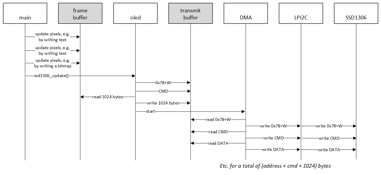
In all I2C examples so far, a hardware or software FIFO was used. In the sequence diagram above, a FIFO is not even mentioned. In this example, the 1024 byte frame buffer is actually first copied to a transmit buffer, and preceded by additional data, such as the target address and commands. This makes it easier to transmit all data with DMA, because the I2C controller requires 16-bit data (CMD and DATA). This driver is therefore double buffered. Another advantage of double buffering, is that if the main application updates the frame buffer, the transmit buffer will not be updated, unless the ssd1306_update() function is called.
One way to achieve frequent display updates is to use a timer and trigger a DMA transfer several times per second. This should not exceed approximately 40 times per second, because 40 times per second means an interval of 25 ms, which is barely enough to transmit all bytes in FAST mode.
SSD1306 configuration
The SSD1306 controller needs to be configured when it is powered on by sending the appropriate commands. Fortunately, the datasheet provides an example in terms of a software configuration flowchart. This is used as an inspiration for sending the initialisation commands when the application is started.
Q2 Browse the example project and find the array of initialisation commands.
The oled display contains a lot of features that can be controlled by sending the appropriate commands. An example is setting normal or inverse display.
Q3 What command needs to be transmitted in order to set inverse display?
Oled API
The SSD1306 driver provides the following API. All functions are documented in the source file.
void ssd1306_init(void);
void ssd1306_command(const uint8_t cmd);
void ssd1306_data(const uint8_t data);
void ssd1306_update(void);

void ssd1306_setfont(const char *f);
void ssd1306_setorientation(const uint8_t orientation);
void ssd1306_setinverse(const uint8_t inv);

void ssd1306_clearscreen(void);
void ssd1306_setcontrast(const uint8_t contrast);
void ssd1306_goto(const uint8_t x, const uint8_t y);
void ssd1306_setpixel(const uint8_t x, const uint8_t y, const pixel_value_t val);

void ssd1306_putchar(const char c);
void ssd1306_putstring(const uint8_t x, const uint8_t y, const char *str);

void ssd1306_drawline(uint8_t x0, uint8_t y0, uint8_t x1, uint8_t y1);
void ssd1306_drawbitmap(const unsigned char *bitmap);

void ssd1306_terminal(const char *str);
The main application demonstrates how to use several driver functions.
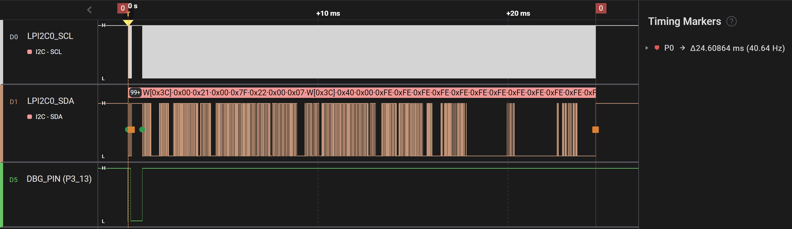
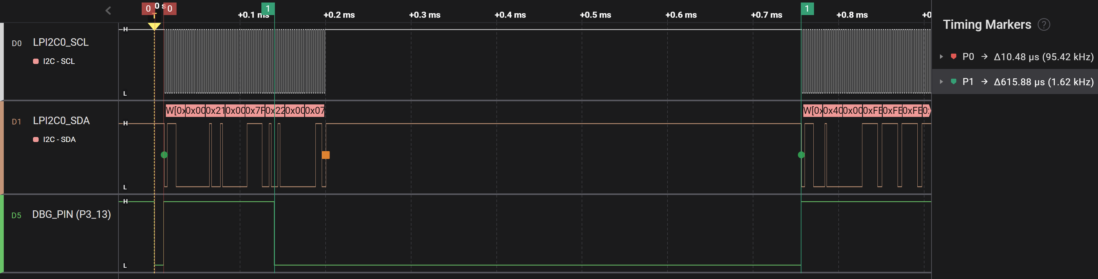
Finally, the following timing diagrams show the data transmissions. A debug pin was added and pulled low while the CPU was busy setting up the I2C DMA transfer. Instead of almost 25 ms, the CPU is busy for not even 1 ms, while the DMA controller transfers the data. And upon close inspection of the timing diagram, the majority of the 1 ms is spend in a delay that is required by the oled display between two transfers. This delay is implemented wit a for-loop, so timing depends on optimization settings. This could be tuned further, because the required delay is only 2 us.
SSD1306 DMA total:
SSD1306 DMA detail:
Assignment
Change the example application to display your name and student number. Familiarize yourself with the API by trying new fonts, drawing lines and/or drawing new bitmaps.