Assignment - Rotary encoder
Resources: ese_shieldv3_examples\encoder\gpio
Goal
To practice with the modules discussed so far.
Hardware requirements
- FRDM-MCXA153 board
- Rotary encoder, such as available on Shield V3 or Mikroe-1824 add-on board
- Type-C USB cable
Note. When using the Mikroe add-on board, different pins must be used!
Functional requirements
The application uses the RGB LED and a rotary encoder. It must implement the following functional requirements.
-
The application keeps track of the number of CW and CCW pulses.
a. pulses = 0: RGB LEDs off.
b. pulses > 0: Green LED on; Red LED off.
c. pulses < 0: Green LED off; Red LED on.
-
A CW pulse increments the number of pulses by 1.
- A CCW pulse decrements the number of pulses by 1.
- Pressing the encoder switch resets the pulses to 0.
- After a microcontroller reset, pulses is reset to 0.
Architecture
The Shield V3 shows an example of how to connect the hardware parts.
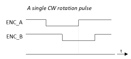
The ENC_A and ENC_B signals encode the rotation direction. An example timing diagram for a single clockwise (CW) rotation pulse:
And an example timing diagram for a single counter clockwise (CCW) rotation pulse:
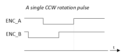
Notice from both timing diagrams that on a rising edge of ENC_A, the sampled logic value of ENC_B is different for CW and for CCW rotations.
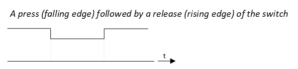
The ENC_SW signal reflects the logic state of the encoder switch as follows:
API
In order to create the functional requirements, the following API functions are prepared.
/*!
 * \brief Initializes the RGB LED pins
 *
 * - Red LED   | P3_12 | GPIO output
 * - Green LED | P3_13 | GPIO output
 * - Blue LED  | P3_0  | GPIO output
 */
void gpio_output_init(void);
/*!
 * \brief Initializes the encoder pins
 *
 * - ENC_A  | P3_31 | GPIO input with interrupts enabled on rising edges
 * - ENC_B  | P2_7  | GPIO input
 * - ENC_SW | P1_6  | GPIO input with interrupts enabled on both edges
 */
void encoder_init(void);
/*!
 * \brief Resets the counted pulses.
 *
 * Resets the internal pulses counter to 0.
 */
void encoder_reset(void);
/*!
 * \brief Returns the number of pulses in CW or CCW direction since last reset
 *
 * The function keeps track of the CW and CCW pulses. For every CW pulse, an
 * internal counter is incremented. For every CCW pulse, that same counter is
 * decremented.
 *
 * Meaning:
 *   - If the function returns 0, no pulses were counted or as much CW pulses as
 *     CCW pulses
 *   - If the function returns a value < 0, that much more number of CCW pulses
 *     were detected.
 *   - If the function returns a value > 0, that much more number of CW pulses
 *     were detected.
 *
 * \return The number of pulses counted since last reset
 */
int32_t encoder_pulses(void);
/*!
 * \brief Detects if the switch was pressed.
 *
 * This firmware driver remembers if the switch was pressed with an internal
 * flag. When this function is called, it resets the internal flag.
 *
 * \return True if the switch was pressed.
 */
bool encoder_sw_pressed(void);
/*!
 * \brief Detects if the switch was released.
 *
 * This firmware driver remembers if the switch was released with an internal
 * flag. When this function is called, it resets the internal flag.
 *
 * \return True if the switch was released.
 */
bool encoder_sw_released(void);
Implementation tips
- Start with the RGB LED GPIO output pins. Verify in main that the RGB works as expected.
For the encoder rotation detection:
- Configure ENC_A and ENC_B pins for GPIO input.
- Configure ENC_A pin to generate interrupts on rising edges.
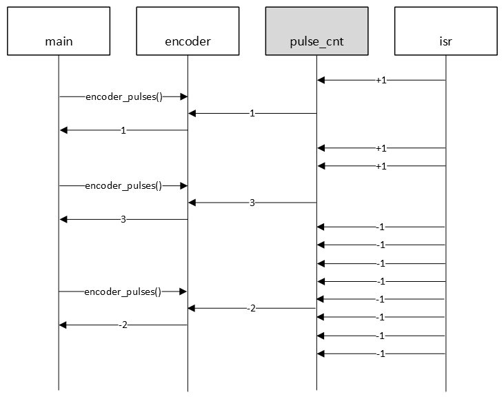
- When such an interrupt occurs, sample the logic input value of the ENC_B pin:
- if ENC_B pin = 0, then CW rotation, so internal counter pulse_cnt + 1
- if ENC_B pin = 1, then CCW rotation, so internal counter pulse_cnt - 1
This behaviour is illustrated in the following sequence diagram.
For the encoder switch:
- Configure ENC_SW for GPIO input.
- Configure ENC_SW pin to generate interrupts on falling edges.
- When such an interrupt occurs, set an internal boolean flag sw_pressed indicating a SW press.
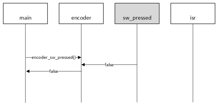
The following sequence diagram illustrates this behaviour for when the switch was pressed.
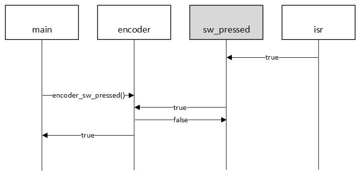
Or, the same example, but now when the switch was not pressed.