I2C Introduction
Resources: none
Goal
To understand the I2C communication protocol.
Communication protocol
The I2C interface is invented by Philips in the 80’s. It is used to connect several low speed peripheral devices to a microcontroller/computer with a two wire interface. With the I2C interface each device can be master and/or slave because both lines are bidirectional. Since I2C specification revision 7.0 this terminology was updated to controller and target.
The interface consists of two physical connections called Serial Data (SDA) and Serial Clock (SCL). The signals use open-drain I/O's, so external pullup resistors must be added to make sure that a logic 1 equals Vdd.
I2C is a multi-controller and multi-target interface. This implies that there must be an addressing mechanism. The following figure shows the interconnections to an I2C bus.
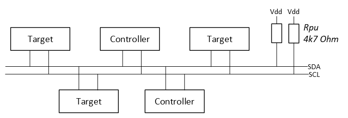
The I2C protocol states that a controller initiates a data transfer with a so-called ‘START condition’ and then immediately transmits the target address. If there are multiple I2C targets present on the same bus, only the addressed target will respond.
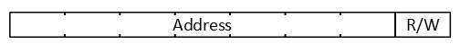
The address is coded in 7-bits (or 10-bits) and an additional bit (LSB) is added to let the target know what the controller wants:
- LSB = logic 0: the controller wants to write data to the target
- LSB = logic 1: the controller wants to read data from the target
In rest, both SDA and SCL are high (Vdd). The following will happen when a controller initiates an I2C transfer:
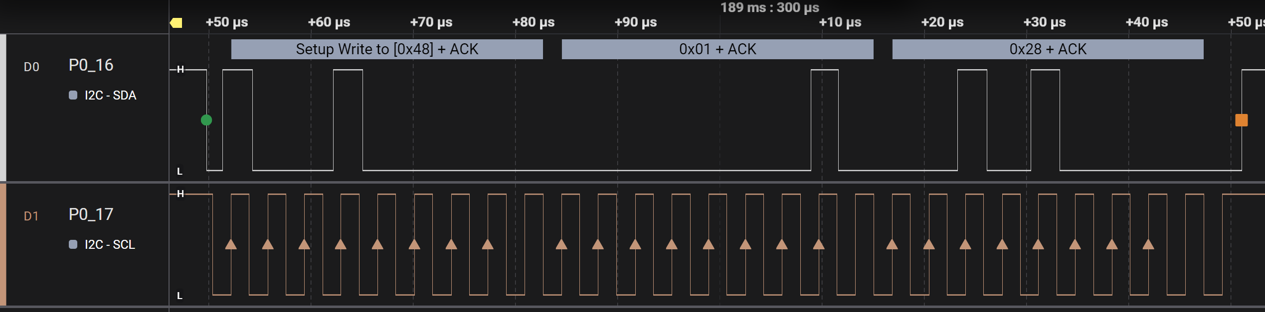
- A START condition is generated by the controller, meaning the SDA line will be pulled low while the SCL is still high (see most left green dot in the figure below).
- Then, with the frequency of SCL, 8-bit data will be transferred to all targets, but only the target with the matching hardware address will respond, accordingly the LSB (read or write). In the example below, a write transfer is initiated to a target with address 0x48.
- This transfer is acknowledged by the target device. During the ninth clock pulse it will pull down the SDA line. This is also known as the ACK bit. Then a new transfer can be initiated by the controller, in the example below 0x01 is transmitted to the target. This transfer is also acknowledged by the target.
- More data can be transferred and each transfer will be acknowledged by the target. In this example 0x28.
- After the last transfer the controller will generate a STOP condition, meaning the SDA line is released (rising edge) by the controller while leaving the SCL high (see the red square in the figure below).
Reading from an I2C target is a little different. Before reading, the controller needs to tell the target what it wants to read. This means an initial write operation, followed immediately by a read operation.
So the following will happen when a controller initiates an I2C transfer for reading data:
- The first three steps are the same as above:
- START condition
- transmit address + write (LSB=0)
- ACK by target
- Instead of a new transfer, a so-called REPEATED START condition is generated (the second green dot in the figure below).
- The same target address is transmitted, however, now with the LSB set (LSB=1), indicating that the controller wants to read data from the target.
- This is ACKnowledged by the target.
- Next, the controller generates 8 clock pulses and the target will write data on the SDA line. This is 0x28 in the figure below.
- The data is not acknowledge, because it is transmitted by the target.
- After the last transfer the controller will generate a STOP condition (the red square in the figure below).
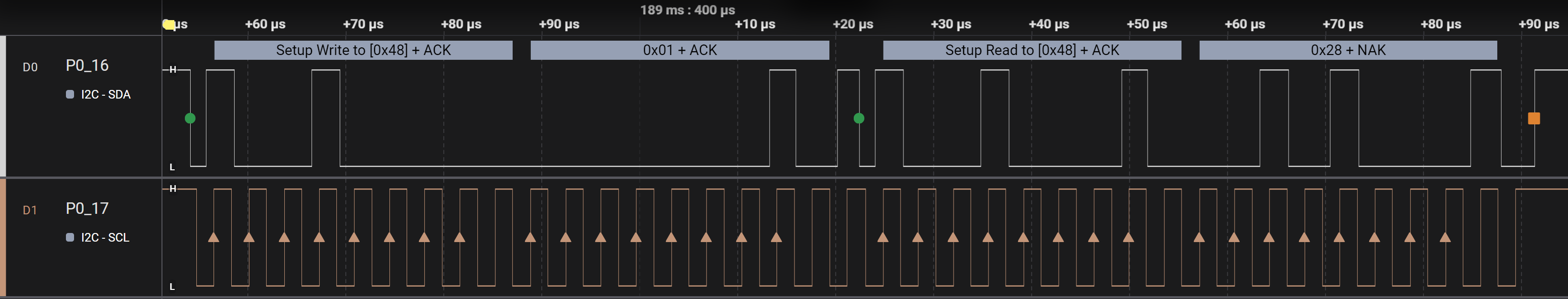
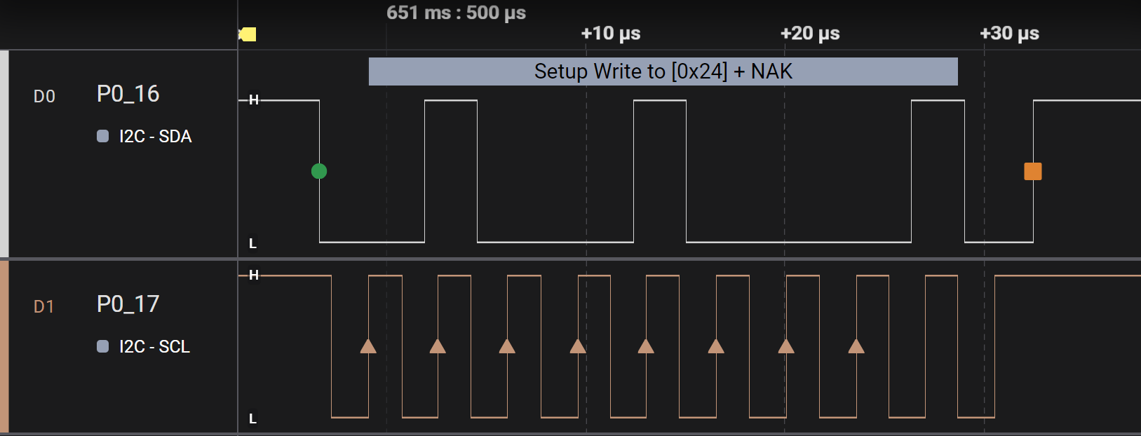
What happens if there is no device with the transmitted address on the I2C bus? The controller sends the address + R/W, but there will be no ACK as depicted in the following image: