NVIC
Resources: none
Goal
To understand how the NVIC handles interrupts and use CMSIS to configure the NVIC.
Required hardware
- None
Introduction
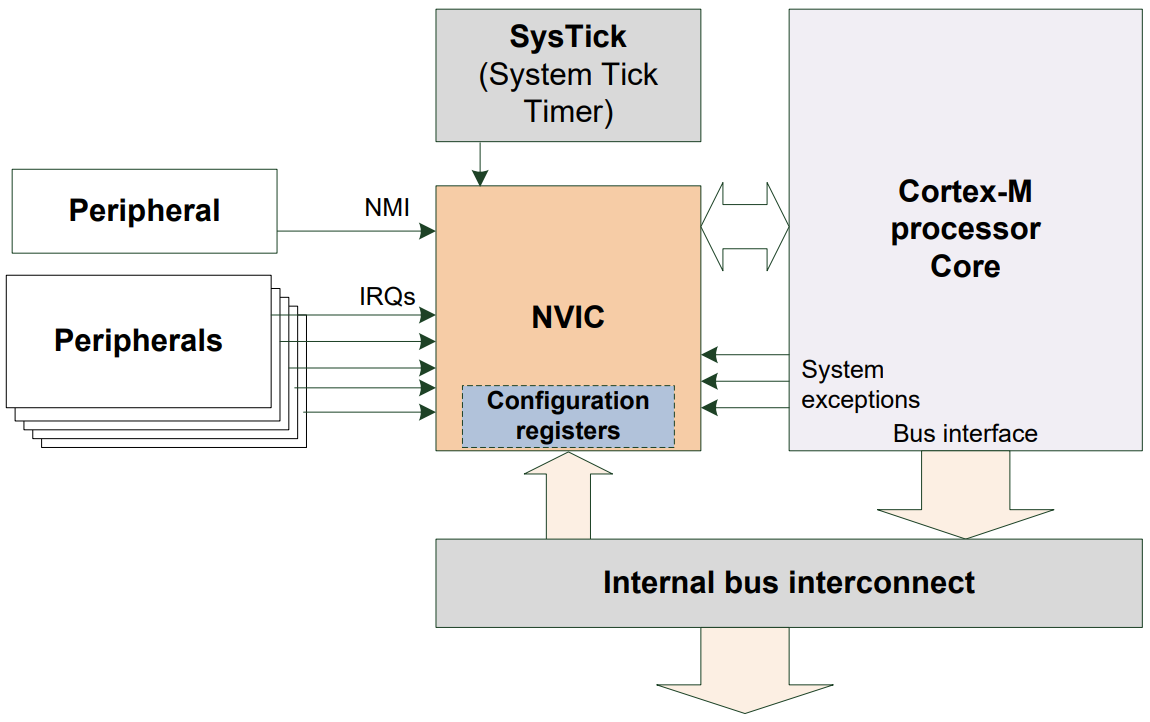
The Nested Vectored Interrupt Controller (NVIC) handles the priority management and masking of interrupts and exceptions. The NVIC is closely coupled with the core as depicted and described in this white paper:
Each interrupt can be in one of the following states:
- Inactive
The interrupt is not active and not pending
- Active
Indicates that this interrupt is being serviced
- Pending
Indicates that an interrupt is waiting to be serviced.
- Active and pending at the same time
The interrupt is being serviced by the core and there is a pending exception from the same source
Nesting
The N in NVIC stands for nested. Nested in the context of microcontrollers means that the handling of one interrupt service handler can be interrupted by another interrupt. For example:

Interrupting another interrupt handler is only possible if the latter interrupt has higher priority. The reference manual section 3.3 describes that the MCXA153 supports 8 interrupt priority levels. These 8 levels are recorded in three bits. For the first four IRQ numbers, this is recorded in Interrupt Priority Register 0 (IPR0) as follows:
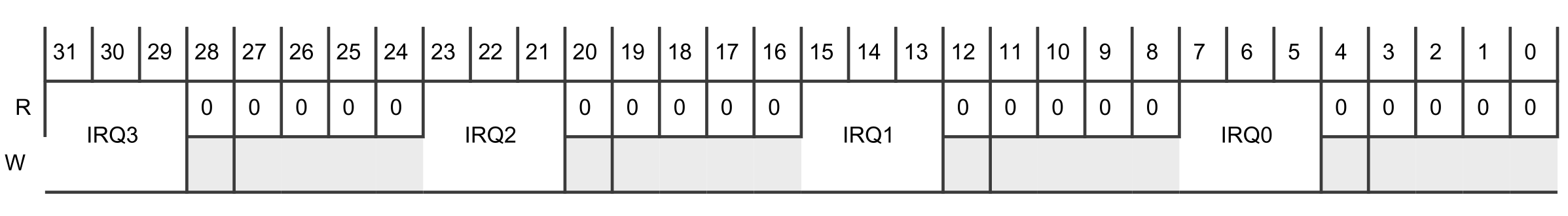
As can be seen in the image, each priority level is recorded in the MSB three bits of a byte. This results in the following priority levels in binary and decimal notation:
0b 000 00000 : 0    -> highest priority
0b 001 00000 : 32
0b 010 00000 : 64
0b 011 00000 : 96
0b 100 00000 : 128
0b 101 00000 : 160
0b 110 00000 : 192
0b 111 00000 : 224  -> lowest priority
Vector
The V in NVIC stands for vectored. Vectored in the context of microcontrollers means that the addresses of the interrupt handlers are stored in a table. In other words, this table stores function pointers (a.k.a. vectors) to the interrupt handlers. As soon as an interrupt is triggered, the microcontroller finds the corresponding address in this table and starts executing the interrupt handler.
The index of an address in this table is also know as the interrupt number (IRQn). The implementation of the entire vector table for the MCXA153 is given in the reference manual in an appendix. An example of a (partial) vector table from one of the example projects is as follows:
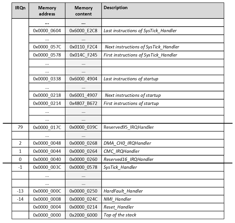
The reference manual contains an appendix called NVIC_configuration.xlsx. In this document the IRQn (NVIC Interrupt ID) of all modules is given. For example, for the GPIO1 module: IRQn=72
The vector table is created by the linker and (normally) stored at the beginning of the flash memory. This is achieved in the examples in the startup file. This startup file uses placeholder names for all interrupt handlers. These are declared with the weak symbol, to denote that if the programmer doesn't provide an interrupt handler, the placeholder implementation should be used.
Special cases of interrupt priority
The NVIC will handle special priority cases as follows:
- New interrupt requested while an interrupt handler is executing?
- New priority higher than current priority?
- New interrupt handler pre-empts current interrupt handler
- New priority lower than or equal to current priority?
- New interrupt held in pending state
- Current handler continues and completes execution
- Previous priority level restored
- New interrupt handled if priority level allows
- New priority higher than current priority?
- Simultaneous interrupt requests and the same priority?
- Lowest interrupt IRQn is serviced first
CMSIS
The NVIC can be read and written by using its registers, similar to all other modules in the microcontroller. However, the NVIC is a module that is available in all Cortex-M microcontrollers. For that reason the CMSIS provides functions to access the NVIC.
Some functions that are often used are:
// Enable a device specific interrupt.
void NVIC_EnableIRQ(IRQn_Type IRQn);

// Set the priority for an interrupt.
void NVIC_SetPriority(IRQn_Type IRQn, uint32_t priority);

// Clear a device specific interrupt from pending.
void NVIC_ClearPendingIRQ(IRQn_Type IRQn);

// Globally enables interrupts.
void __enable_irq();

// Globally disables interrupts.
void __disable_irq();
Microcontroller vendors offer an enumerated type for the IRQn's. So instead of writing
void NVIC_EnableIRQ(31);
for enabling LPUART0 interrupts, the following can be used:
void NVIC_EnableIRQ(LPUART0_IRQn);
Setting the priority of an IRQn can be done in two ways:
- Directly by writing to the IPRn registers.
- By using the CMSIS function NVIC_SetPriority().
There is a difference, because the the CMSIS function assumes a priority value from 0 to 7. Whereas the IPRn registers should have a value as mentioned above. In other words, the following instructions have the same result:
NVIC_SetPriority(GPIO1_IRQn, 3);

NVIC->IPR[GPIO1_IRQn] = 96;
Invalid priority - extra
What happens if (by mistake) the following instruction is executed?
NVIC_SetPriority(GPIO1_IRQn, 96);
What happens next, depends on the implementation of the NVIC_SetPriority() function (see the file CMSIS/Core/Include/core_cm33.h included in all projects):
/**
  \brief   Set Interrupt Priority
  \details Sets the priority of a device specific interrupt or a processor exception.
           The interrupt number can be positive to specify a device specific interrupt,
           or negative to specify a processor exception.
  \param [in]      IRQn  Interrupt number.
  \param [in]  priority  Priority to set.
  \note    The priority cannot be set for every processor exception.
 */
__STATIC_INLINE void __NVIC_SetPriority(IRQn_Type IRQn, uint32_t priority)
{
  if ((int32_t)(IRQn) >= 0)
  {
    NVIC->IPR[((uint32_t)IRQn)]
      = (uint8_t)((priority << (8U - __NVIC_PRIO_BITS)) & (uint32_t)0xFFUL);
  }
  else
  {
    SCB->SHPR[(((uint32_t)IRQn) & 0xFUL)-4UL]
      = (uint8_t)((priority << (8U - __NVIC_PRIO_BITS)) & (uint32_t)0xFFUL);
  }
}
For the MCXA153, __NVIC_PRIO_BITS is defined as 3. This means the provided priority will be bitwise left shifted 8 - 3 = 5 positions. With a value of 96 (=0b01100000), this means: (0b01100000 << 5) = 0b00000000.
The result is that the priority will be set to 0, which is the highest priority.
ISR considerations
When writing ISR's it is considered good practice to:
- Clear an interrupt in both the NVIC and module.
- Keep code as short as possible in the ISR.
- Declare global variables volatile that are used in the ISR to prevent the compiler from optimization.