Assignment - Servo motor
Resources: ese_shieldv3_examples\servo\ctimer
Goal
To practice with the modules discussed so far.
Hardware requirements
- FRDM-MCXA153 board
- Servo motor, can conveniently be connected to the Shield V3 or by using three jumper wires.
- Type-C USB cable
Functional requirements
The application uses a servo motor connected to P3_10. A CTimer must be used to control the servo motor PWM pulse width with 1000 steps precision.
Architecture
The Shield V3 shows an example of how to connect the hardware parts.
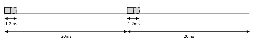
A servo motor typically requires a PWM frequency of 50 Hz and a duty cycle between 1 and 2 ms. as depicted in the following image:
API
In order to create the functional requirements, the following API functions are prepared.
/*!
 * \brief Initializes the servo pins
 *
 * Resources:
 * - SERVO_PWM | P3_10 | CT1_MAT0
 *
 * Configures CTimer1 to generate a PWM signal on MAT0 with a 50 Hz frequency.
 */
void servo_init(void);

/*!
 * \brief Set the servo duty cycle
 *
 * Sets the PWM duty cycle as follows:
 * - 1000 =   0% = 1.0 ms pulse width = servo moves left
 * - 1500 =  50% = 1.5 ms pulse width = servo moves centre
 * - 2000 = 100% = 2.0 ms pulse width = servo moves right
 *
 * \param[in]  value Duty cycle of the PWM signal
 */
void servo_set(int32_t value);
Implementation tips
- Use the reference manual to find out what CTIMER and what match register are connected to P3_10.
- The functional requirements state that the PWM pulse must be controlled with 1000 steps precision. This means that if 1 ms must be divided in 1000 steps, 20 ms must be divided in 20000 steps. And thus, 1 second must be divided in one million steps.
- A CTimer generates an active low PWM signal, whereas the servo motor requires an active high PWM signal. There is no configuration option in the CTimer to generate an inverted PWM, so a software solution needs to be constructed. Tip: match_register = (top - value).
- Use a logic analyzer to verify the generated PWM signal.