LPI2C board-2-board communication
Resources: ese_driver_examples\lpi2c\b2b_controller_interrupt
Goal
To communicate over I2C as a controller with another FRDM-MCXA153 board that is configured as a target.
Hardware requirements
- 2 FRDM-MCXA153 boards
- 2 Type-C USB cables
- Jumper wires
- 4k7 Ohm pullup resistors, available on the Shield V3
Preparing the target
This assignment comes with a prepared target project. This project is located in the same folder as this controller project and is called b2b_target_interrupt. Open this project and program one of the FRDM-MCXA153 boards. Study the source code and find the target I2C address and what messages must be written to the target and what messages can be read from the target. This information is also available in the target's documentation.
Connect the two boards as follows:
| Controller | Target |
|---|---|
| SDA | SDA |
| SCL | SCL |
| GND | GND |
Make sure there is a pullup resistor of 4k7 Ohms connected to both SDA and SCL.
Preparing the controller
When running the provided project, the controller RGB LED will blink red, green, blue, red, green, blue, etc.
Assignment
The target RGB is not blinking. The goal is to send the value of the controller RGB LED to the target, so the target LED follows the controller LED. Also, the controller must read three bytes from the target with a repeated start condition. The following timing diagram shows what the communication should look like as soon as the project is finished.
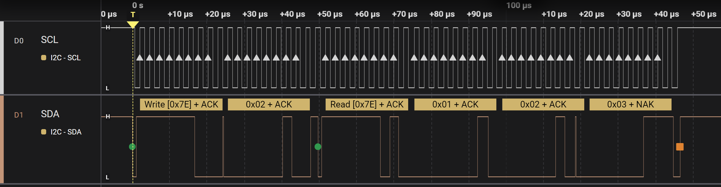
To achieve this goal, the following steps are required. Implement these steps in main.c when the interval has passed so the communication as seen above is transmitted at every interval.
- Wait as long as bus or controller is busy. Check the file lpi2c0_controller_interrupt.h for the available functions to do so.
- Clear all the status flags of the LPI2C. Check one of the example projects how to do so.
- Fill the transmit FIFO by putting in two words. Check the file lpi2c0_controller_interrupt.h for the available functions to do so.
- The first word consists of:
- CMD: Generate (repeated) Start on the I2C bus and transmit the address in DATA[7:0]
- DATA: slave address + write
- The second word consists of:
- CMD: Transmit the value in DATA[7:0]
- DATA: the variable rgb
- The first word consists of:
Check result 1
If implemented correctly, the target board shows the same RGB colour as the controller board does. However, the target board seems to freeze after several seconds. When resetting both boards, it will work again, but only for several seconds.
The reason for this behaviour is that the target sends three bytes for every byte it receives. The controller, however, never reads from the target. This means the transmit FIFO of the target will be full after several bytes. To solve this, the controller should read three bytes directly after every write of the rgb variable. This can be done with a repeated start condition. Add the following words in the transmit FIFO directly after putting in the previous words.
- Fill the transmit FIFO by putting in two more words.
- The first word consists of:
- CMD: Generate (repeated) Start on the I2C bus and transmit the address in DATA[7:0]
- DATA: slave address + read
- The second word consists of:
- CMD: Receive (DATA[7:0] + 1) bytes. DATA[7:0] is used as a byte counter.
- DATA: 2
- The first word consists of:
Check result 2
If implemented correctly, both boards will show the same LED colour. However, after a while, both will stop. The problem is now caused by the controller, because the receive FIFO is filled but never read.
In main, add the following code to make sure that the RXFIFO is read when data is available:
if(lpi2c0_rxcnt() >= 3)
{
    uint8_t data1 = lpi2c0_getword();
    uint8_t data2 = lpi2c0_getword();
    uint8_t data3 = lpi2c0_getword();

    // Check data from target
    if((data1 != 0x01) || (data2 != 0x02) || (data3 != 0x03))
    {
        // Data invalid
        GPIO3->PCOR = (1<<12);
        GPIO3->PSOR = (1<<13);
        GPIO3->PSOR = (1<<0);

        while(1)
        {}
    }
}
Verify that the communications is stable for a long period. Optionally, use a logic analyzer to visualize the result.