CMSIS
Resources: none
Goal
To understand what the CMSIS is and how bits are manipulated in registers in C by using CMSIS.
Required hardware
- None
Introduction
This course aims at teaching how to program the modules of the microcontroller directly through its registers, instead of using driver functions. This will be achieved by making use of the Common Microcontroller Software Interface Standard (CMSIS). One subject of this standard is the naming convention for accessing modules. Microcontroller vendors offer CMSIS compliant header and source files that can be added to a project, which is often automated when creating a new project in the SDE of choice. The benefit of using this naming convention is that accessing registers of peripherals in C is done by simple statements. Most microcontroller vendors use names that are also used in their reference manual and/or datasheet.
The CMSIS naming convention for accessing modules is:
MODULE->REGISTER
For example, setting the CTRL register in the SysTick module to zero is done as follows:
SysTick->CTRL = 0x00000000;
Memory mapped IO
All registers in an ARM Cortex-M microcontroller are memory mapped. This means that every registers is located at a 32-bit address. For example, the SySTick->CTRL register in the MCXA153 microcontroller is located at address 0xE000E010. Writing a 32-bit number to this 32-bit address in C can be done as follows:
*((volatile uint32_t *)(0xE000E010)) = 0x00000000;
This is both unreadable and not portable.
Within the SysTick module, there are a total of four 32-bit registers. These registers are called:
- CTRL - Control and Status register
- LOAD - Reload value register
- VAL - Current value register
- CALIB - Calibration register
These register are conveniently grouped in memory. CMSIS takes advantage of the fact that a struct in C is a way to group variables. The registers memory layout of the SysTick module can therefore be represented as a struct:
typedef struct
{
  volatile uint32_t CTRL;   /*!< Offset: 0x000 (R/W)  SysTick Control and Status Register */
  volatile uint32_t LOAD;   /*!< Offset: 0x004 (R/W)  SysTick Reload Value Register */
  volatile uint32_t VAL;    /*!< Offset: 0x008 (R/W)  SysTick Current Value Register */
  volatile const uint32_t CALIB;  /*!< Offset: 0x00C (R/ )  SysTick Calibration Register */
} SysTick_Type;
The base address in memory of this struct will be the address of the first field in the struct, being the CTRL register in this example. And the address of the CTRL register is known, because this is described in the reference manual (or in this case the ARMv8-M documentation, because this is a core register). A more meaningful name for the base address of the module is defined as follows:
#define SysTick ((SysTick_Type *) 0xE000E010 )
This means: SysTick is a pointer pointing to a SysTick_Type struct at address 0xE000E010.
Accessing one of the fields can thus be achieved by using the pointer to a struct
dereference operator: ->
For example:
SysTick->CTRL = 0x00000000;
Cortex-M microcontroller vendors offer comprehensive header files for their devices with CMSIS compliant defines for all the modules and registers.
Bit manipulation
Bits in register are manipulated with the C bitwise operators as follows:
// Assignment: assign a value to all bits in a register
MODULE->REGISTER = (0x00010001);
// Bitwise-or: set bits in a register and leave all others unchanged
MODULE->REGISTER |= (0x00010001);
// Bitwise-and: clear bits in a register and leave all others unchanged
MODULE->REGISTER &= ~(0x00010001);
// Bitwise ex-or: toggle bits in a register and leave all others unchanged
MODULE->REGISTER ^= (0x00010001);
Bit field masks
Instead of using magic numbers (such as 0x00010001 in the example above), CMSIS also provides a convention for accessing bit fields in a register. The convention describes the following three defines for each bit field:
// A 32-bit mask with logic 1s at every location of the bit field
MODULE_REGISTER_BITFIELD_MASK

// The bit position of the LSB of the bit field
MODULE_REGISTER_BITFIELD_SHIFT

// A macro to shift the number x to the bit fields location in the register.
// The macro also makes sure that if an invalid number is written (i.e. too
// large for the bit field), all bits outside the bit field boundary are
// set to logic 0.
MODULE_REGISTER_BITFIELD(x)
As an example, let's have a look at the TCR register. It's description diagram is taken from the reference manual.
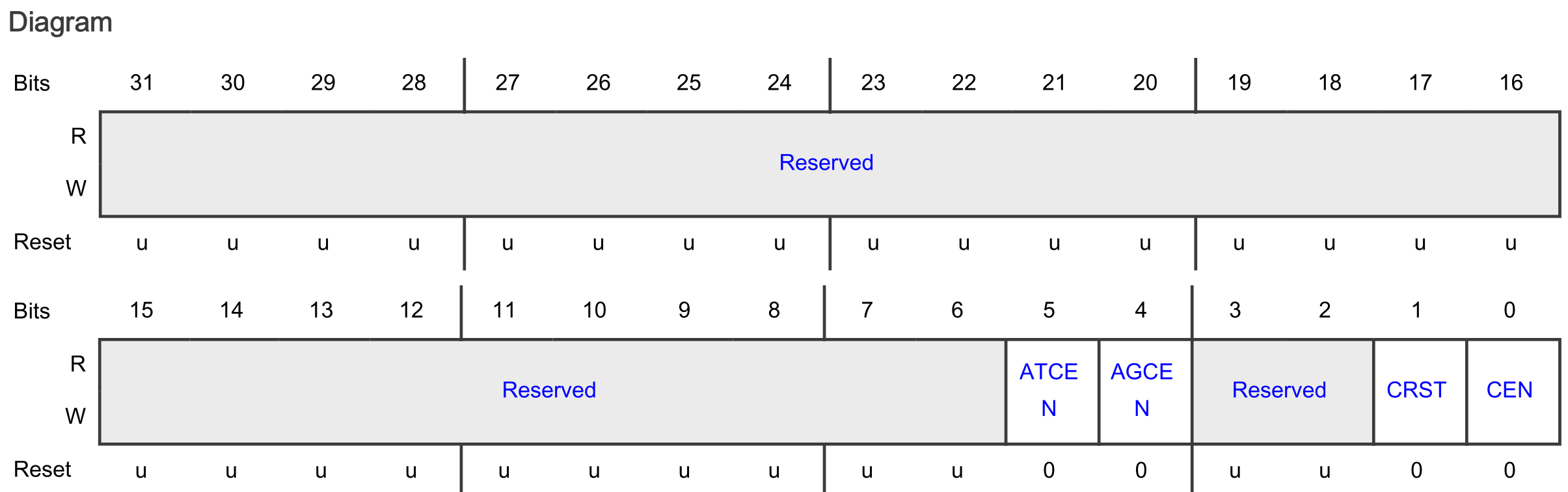
According to the convention, the following defines are available for the CEN bit field in this TCR register:
#define CTIMER_TCR_CEN_MASK   (0x1U)
#define CTIMER_TCR_CEN_SHIFT  (0U)
#define CTIMER_TCR_CEN(x)     (((uint32_t)(((uint32_t)(x)) << CTIMER_TCR_CEN_SHIFT)) & CTIMER_TCR_CEN_MASK)
These defines can for example be used as follows.
// Set the CEN bit field in the TCR register in the CTIMER1 module and leave
// all other bits unchanged. Notice that all three instructions have the same
// result!
CTIMER1->TCR |= CTIMER_TCR_CEN(1);
CTIMER1->TCR |= (1 << CTIMER_TCR_CEN_SHIFT);
CTIMER1->TCR |= CTIMER_TCR_CEN_MASK;

// Reset the CEN bit field in the TCR register in the CTIMER1 module and leave
// all other bits unchanged. Notice that all three instructions have the same
// result!
CTIMER1->TCR &= ~(CTIMER_TCR_CEN(1));
CTIMER1->TCR &= ~(1 << CTIMER_TCR_CEN_SHIFT);
CTIMER1->TCR &= ~(CTIMER_TCR_CEN_MASK);
As a reference, here are several examples for other registers and bits in the MCXA153 microcontroller.
// Set the PCS bit field in the PSR register of LPTMR0 module to 3 and reset
// all others!
LPTMR0->PSR = LPTMR_PSR_PCS(0b11);

// Set the LK bit field in PCR 0 register of PORT3 and reset all other bits!
PORT3->PCR[0] = PORT_PCR_LK(1);

// Check if the TDRE bit field in the STAT register of the LPUART0 module is
// not equal to zero.
if((LPUART0->STAT & LPUART_STAT_TDRE_MASK) != 0)

// Check if the BBF bit field or the MBF bit field in the MSR register of the
// LPI2C module is not equal to zero.
while((LPI2C0->MSR & (LPI2C_MSR_BBF_MASK | LPI2C_MSR_MBF_MASK)) != 0)
Extra
Curious how the three defines for bit field masks evaluate at compile time? Read this!