Low-Power Timer
Resources: ese_driver_examples\lptmr\match_interrupt
Goal
To know what the LPTMR module is and how to use the LPTMR module for generating interrupts at a fixed interval.
LPTMR features
The MCXA153 has one instance of the LPTMR module. It is called LPTMR0. The LPTMR is described in the reference manual chapter 34.
Some characteristics of the LPTMR module are:
- 32-bit counter.
- Can be clocked from one of four sources determined by the PCS bit field in the LPTMR0->PSR register.
- The LPTMR allows the maximum clock frequency of 25 MHz.
- In low-power modes, LPTMR continues to operate normally.
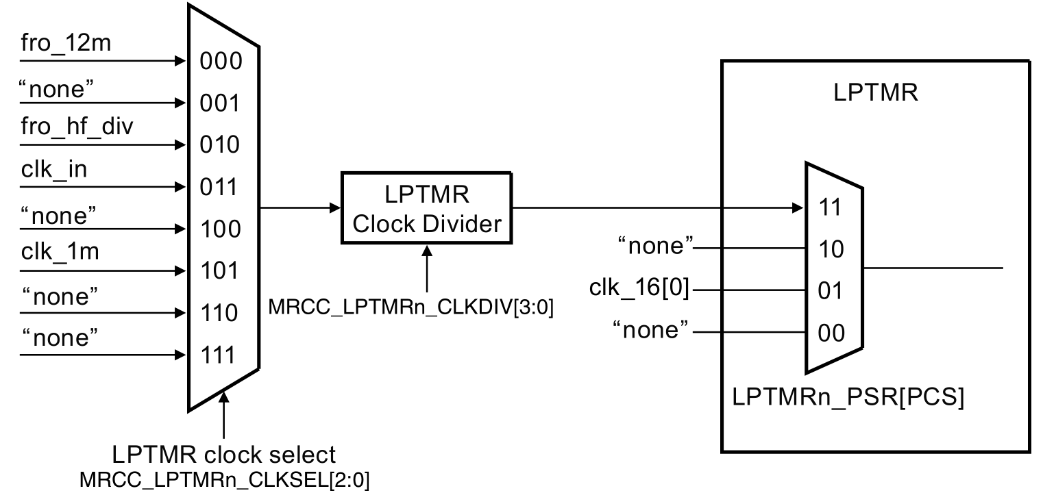
LPTMR clocking
Clocking the LPTMR is established by configuring several bits in registers of the MRCC- and LPTMR module. This is depicted in the following image.
An example
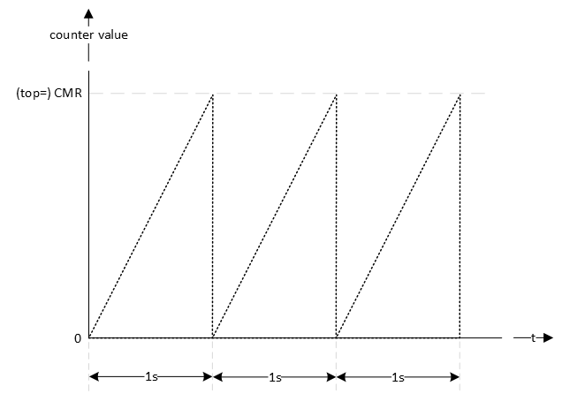
In this example, the LPTMR is configured to generate an interrupt every second. This is depicted in the following timing diagram. CMR is the compare register and when the counter value matches the CMR register, the counter should reset.
First the clock source for the timer should be established. This is application dependent, but let's choose the CLK_1M. Dividing this clock by 1 million generates an interrupt every second. The reference manual chapter 34.5 describes how to initialize LPTMR0.
void lptmr0_init(void)
{
    // Set clock source
    // MUX: [101] = CLK_1M
    MRCC0->MRCC_LPTMR0_CLKSEL = MRCC_MRCC_LPTMR0_CLKSEL_MUX(0b101);

    // Set clock divider
    // HALT: [0] = Divider clock is running
    // RESET: [0] = Divider isn't reset
    // DIV: [0000] = divider value = (DIV+1) = 1
    MRCC0->MRCC_LPTMR0_CLKDIV = 0;

    // From section 34.5 Initialization (NXP, 2024)
    //
    // Perform the following procedure to initialize LPTMR:
    // 1. Configure Control Status (CSR) for the selected mode and pin
    //    configuration, when CSR[TEN] is 0. This resets the counter and clears
    //    the flag.
    // 2. Configure Prescaler and Glitch Filter (PSR) with the selected clock
    //    source and prescaler or glitch filter configuration.
    // 3. Configure Compare (CMR) with the selected compare point.
    // 4. Write 1 to CSR[TEN] to enable LPTMR.

    // 1.
    //
    // - TDRE : [0] = Timer DMA request disable
    // - TCF : [1] = Clears the Timer Compare Flag
    // - TIE : [0] = Timer interrupt disable
    // - TPS : [00] = Timer Pin Select is not used, leave at default value
    // - TPP : [0] = Timer Pin Polarity is not used, leave at default value
    // - TFC : [0] = CNR is reset whenever TCF is set
    // - TMS : [0] = Time Counter mode
    // - TEN : [0] = LPTMR is disabled
    LPTMR0->CSR = LPTMR_CSR_TCF(1);

    // 2.
    //
    // - PRESCALE : [0000] = n.a.
    // - PBYP : [1] = Prescaler and glitch filter disable
    // - PCS : [11] = Clock 3 is Combination of clocks configured in
    //                MRCC_LPTMR0_CLKSEL[MUX] field in SYSCON module. The Clock
    //                frequency must be less than 25 MHz to be used as a clock
    //                for the Low Power Timers.
    LPTMR0->PSR = LPTMR_PSR_PBYP(1) | LPTMR_PSR_PCS(0b11);

    // 3.
    //
    // Generate an interrupt every second
    LPTMR0->CMR = 1000000-1;

    // 4.
    //
    // - TDRE : [0] = Timer DMA request disable
    // - TCF : [1] = Clears the Timer Compare Flag
    // - TIE : [1] = Timer interrupt enable
    // - TPS : [00] = Timer Pin Select is not used, leave at default value
    // - TPP : [0] = Timer Pin Polarity is not used, leave at default value
    // - TFC : [0] = CNR is reset whenever TCF is set
    // - TMS : [0] = Time Counter mode
    // - TEN : [1] = LPTMR is enable
    LPTMR0->CSR = LPTMR_CSR_TCF(1) | LPTMR_CSR_TIE(1) | LPTMR_CSR_TEN(1);

    // Enable Interrupts
    NVIC_SetPriority(LPTMR0_IRQn, 0);
    NVIC_ClearPendingIRQ(LPTMR0_IRQn);
    NVIC_EnableIRQ(LPTMR0_IRQn);
}
The interrupt handler is implemented as follows. The name of the handler is defined in the startup file.
void LPTMR0_IRQHandler(void)
{
    // Clear pending IRQ
    NVIC_ClearPendingIRQ(LPTMR0_IRQn);

    // Clear status flag by writing 1
    LPTMR0->CSR |= LPTMR_CSR_TCF_MASK;

    // Handle the event
    lptmr0_timeout_flag = true;
}
Notice the use of the global variable lptmr0_timeout_flag. This flag can be checked in the main application. The following example checks if the flag is true, set it to false en toggle the green LED.
while(1)
{
    // LPTMR flag true?
    if(lptmr0_timeout_flag == true)
    {
        // Set it false
        lptmr0_timeout_flag = false;

        // Toggle green LED
        GPIO3->PTOR = (1<<13);
    }
}
Assignment
There is more than one way to slow down the generation of interrupts. For example, for generating interrupts with an interval twice as long:
- Set the functional divider to 2, by setting the DIV bit field to 1 in the MRCC0->MRCC_LPTMR0_CLKDIV register.
- Enable and set the prescaler to 2 in the LPTMR0->PSR register.
- Double the value written in the LPTMR0->CMR register.
Implement all of the above. If correct, the green LED toggles approximately every 8 seconds.
Note
Although not used in this example project, reading the LPTMR counter value is different compared to the other timers. This is what is mentioned in the reference manual in section 34.3.5:
You cannot initialize CNR but can read it at any time. On each read of CNR, you must first write a value to it. This synchronizes and registers the current value of CNR into a temporary register. The contents of the temporary register are returned on each read of CNR.
So, reading the counter value is done as follows:
// Reading the CNR value requires that it is written first (see reference manual
// section 34.3.5)
LPTMR0->CNR = 0;
uint32_t cnr_value = LPTMR0->CNR;