SPI - introduction
Resources: none
Goal
To understand the SPI communication protocol.
Communication protocol
The Serial Peripheral Interface (SPI) is a peer-to-peer interface. When compared to I2C, this means SPI doesn't need addressing. In order to address multiple devices a chip select is part of the interface. The following image depicts the physical connections:
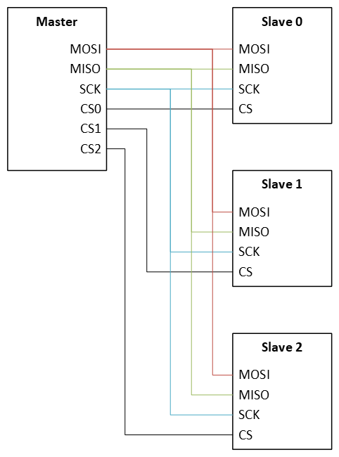
The abbreviations mean:
- MOSI: Master Out - Slave In
- MISO: Master In - Slave Out
- SCK: Serial clock
- CSn: Chip Select n
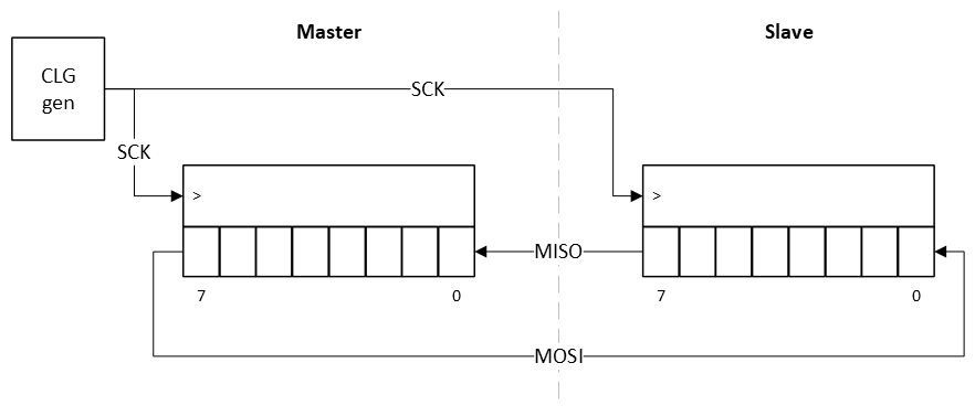
From a data path perspective, the following block diagram shows 8-bit frame size communication between a master and a slave. One can think of this as two shift registers that exchange data at the rate of the SCK signal. Usually, the MSB is transmitted first.
For example, if the master transmits 0xAA and the slave transmits 0x55, the following timing diagram will be generated:
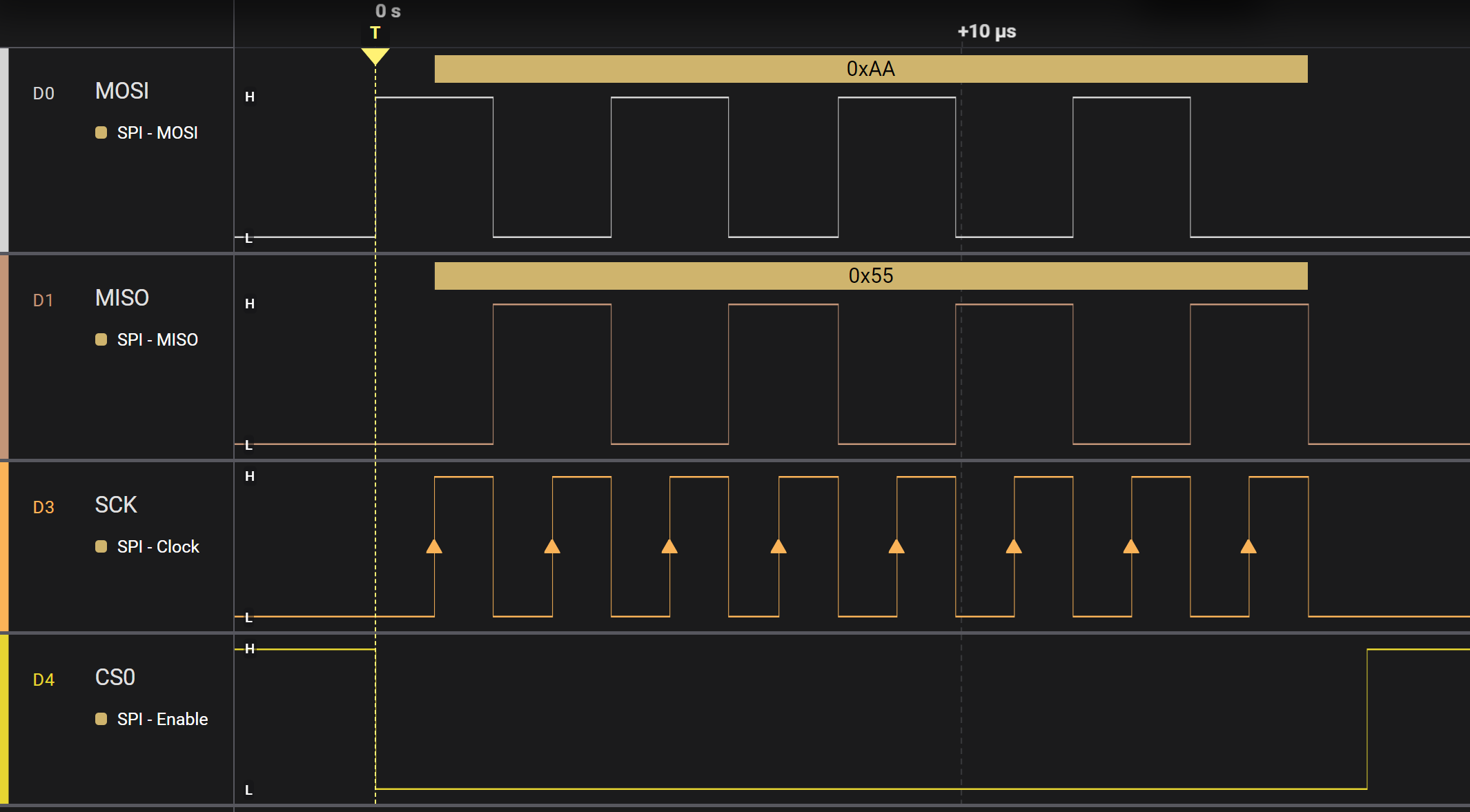
The timing diagram shows that:
- The CSn line is active low, meaning that a slave is selected by pulling the line low.
- On every rising edge of SCK, data from the master is latched by the slave and vice versa.
- At the end of the transfer the CSn line is pulled high.
Although this is a basic example, there are numerous configuration settings that might be applied. Examples are:
- Frame size
- Clock frequency
- Clock polarity
- Clock phase
- Chip select is active high instead of low