GPIO input - interrupt
Resources: ese_driver_examples\gpio\input_interrupt
Goal
Know how to initialize and read a digital input pin by using interrupts in the GPIO module.
Initialization
It takes the following steps to configure P1_7 (SW3) for GPIO:
- Enable the PORT1 and GPIO1 modules in the MRCC module.
-
Initialize P1_7 for GPIO function in the PORT1 module.
No additional action is needed, because the default direction of P1_7 is input. These steps are exactly the same when compared to the polling example.
Using interrupts on a GPIO input pin requires two additional steps:
-
Enable the desired interrupt in the GPIO module.
- Enable GPIO1 interrupts in the NVIC module.
These steps are explained in more detail in the following sections.
1. Enable the PORT1 and GPIO1 modules
// Enable modules and leave others unchanged
// PORT1: [1] = Peripheral clock is enabled
// GPIO1: [1] = Peripheral clock is enabled
MRCC0->MRCC_GLB_CC0_SET = MRCC_MRCC_GLB_CC0_PORT1(1);
MRCC0->MRCC_GLB_CC1_SET = MRCC_MRCC_GLB_CC1_GPIO1(1);

// Release modules from reset and leave others unchanged
// PORT1: [1] = Peripheral is released from reset
// GPIO1: [1] = Peripheral is released from reset
MRCC0->MRCC_GLB_RST0_SET = MRCC_MRCC_GLB_RST0_PORT1(1);
MRCC0->MRCC_GLB_RST1_SET = MRCC_MRCC_GLB_RST1_GPIO1(1);
2. Initialize P1_7 for GPIO function
// Configure pin P1_7
// LK : [1] = Locks this PCR
// INV: [0] = Does not invert
// IBE: [1] = Digital Input Buffer Enable, otherwise pin is used for analog
//            functions
// MUX: [0000] = Alternative 0 (GPIO)
// DSE: [0] = low drive strength is configured on the corresponding pin,
//            if the pin is configured as a digital output
// ODE: [0] = Disables
// SRE: [0] = Fast
// PE:  [0] = Disables
// PS:  [0] = n.a.
PORT1->PCR[7] = PORT_PCR_LK(1) | PORT_PCR_IBE(1) | PORT_PCR_MUX(0);
3. Enable the desired interrupt in the GPIO module.
The GPIO module has an Interrupt Control Register (ICR) for each pin. These registers are organized in an array, so the ICR register for P1_7 is used as follows:
GPIO1->ICR[7]
This register contains two bit fields as can be seen in the reference manual.
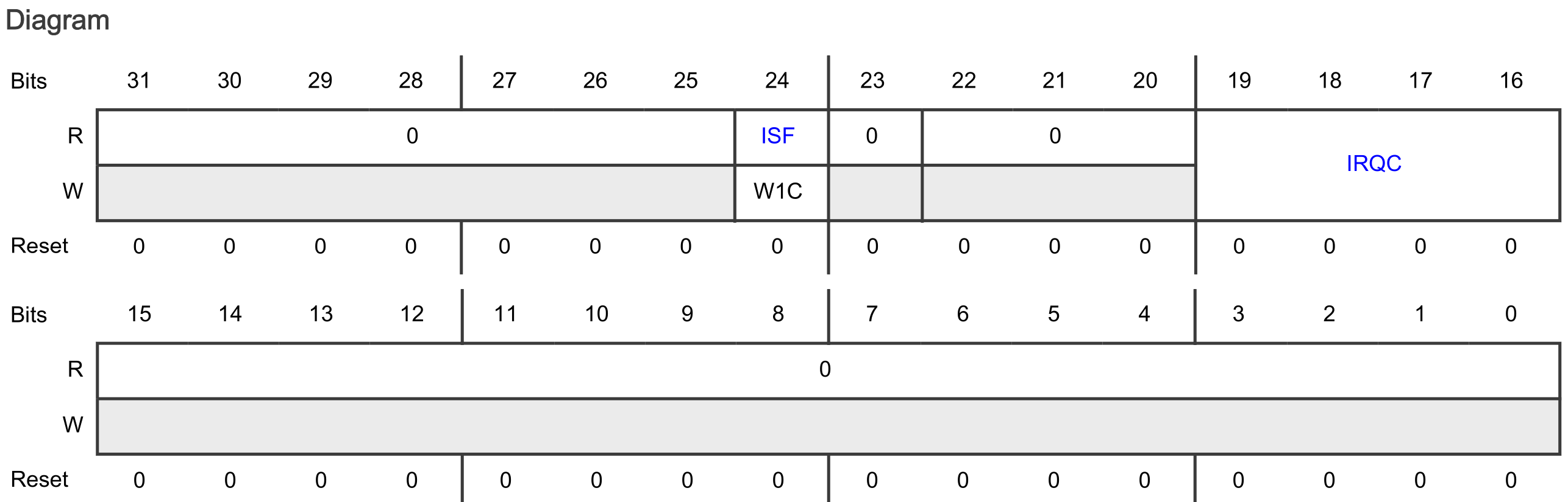
The bit fields are:
- ISF
- Means: Interrupt Status Flag
- Indicates whether the configured interrupt is detected. The pin interrupt configuration is valid in all digital pin muxing modes.
- The ISF bit field shows the text W1C. W1C means Write 1 to clear (w1c). See reference manual paragraph 1.5.4.
- The Interrupt Status Flag Register 0 (ISFR0) can also be used to check the interrupt status of P1_7. See reference manual paragraph 12.7.1.15
- IRQC
- The IRQC bit field contains 4 bits, giving a total of 16 ISF and DMA request configuration options.
- Out of reset, the IRQC bit field is 0b0000. Checking the IRQC configuration
- description in the reference manual: 0000b means that ISF is disabled.
Configuring P1_7 for setting the ISF and generating an interrupt on falling edges is done as follows:
// ISF: [1] = Clear the flag
// IRQC : [1010] = ISF and interrupt on falling edge
GPIO1->ICR[7] = GPIO_ICR_ISF(1) | GPIO_ICR_IRQC(0b1010);
4. Enable GPIO1 interrupts in the NVIC module.
Enabling interrupts for GPIO1 in the NVIC:
// Enable GPIO1 interrupts
NVIC_SetPriority(GPIO1_IRQn, 3);
NVIC_ClearPendingIRQ(GPIO1_IRQn);
NVIC_EnableIRQ(GPIO1_IRQn);
Interrupt handler
The interrupt handler for GPIO handles the interrupt request. The following must be done:
- Clear the interrupt in the NVIC.
- The same interrupt handler is executed for all GPIO1 pins. Check to make sure the interrupt was triggered by P1_7 (although strictly speaking, this is not necessary in this example as there is only one pin generating an interrupt).
- Clear the interrupt in the GPIO module.
- Handle the event.
The result is as follows:
void GPIO1_IRQHandler(void)
{
    // Clear the interrupt
    NVIC_ClearPendingIRQ(GPIO1_IRQn);

    // Interrupt handler triggered by P1_7?
    if((GPIO1->ISFR[0] & GPIO_ISFR_ISF7(1)) != 0)
    {
        // Clear the flag
        GPIO1->ISFR[0] = GPIO_ISFR_ISF7(1);

        // Handle the event
        cnt++;
    }
}
Note the use of a global variable called cnt. This variable is incremented on every interrupt generation. This is a global variable declared as follows:
static volatile uint32_t cnt = 0;
This variable is declared static, because the scope is limited to this file.
This variable is declared volatile, because the variable can change outside normal program flow (because it is used in an ISR). The compiler should not optimize any read/write operations.
Assignment
Change this example so it uses SW2 and the blue RGB LED.
Some tips:
- Find the pin that is connected to SW2 in the board schematic.
- Another GPIO module also requires another interrupt handler.