Solution
Solution to the assignment.
Q1
Append the character to the transmit fifo.
// Wait for space to open up
while(!f_push(&tx, (uint8_t)data))
{}
Enable transmit interrupts.
// Enable TDRE interrupt
LPUART0->CTRL |= LPUART_CTRL_TIE(1);
Wait for the interrupt to occur. In the interrupt handler, read data from the transmit fifo and transmit this data via the LPUART0->DATA register.
// Send another character?
if(f_pop(&tx, &c))
{
    LPUART0->DATA = c;
}
If there is no more data, disable transmit interrupts.
else
{
    // FIFO is empty so disable TDRE interrupt
    LPUART0->CTRL &= ~(LPUART_CTRL_TIE(1));
}
Q2 Wait for space to open up.
Q3
Wait for an interrupt to occur. In the interrupt handler, read data from the LPUART0->DATA register and put it in the receive fifo.
// Read data
c = (uint8_t)(LPUART0->DATA);

// Put in receive FIFO
if(!f_push(&rx, c))
{
    // Error: receive FIFO full!!
    // Should not happen, so freeze the system. Update FIFO size to
    // match your application.
    while (1)
    {}
}
Provide a function to check if data is available in the receive fifo.
uint32_t lpuart0_rxcnt(void)
{
    return f_cnt(&rx);
}
If data is read, return the first item from the fifo.
int lpuart0_getchar(void)
{
    uint8_t c=0;

    // Wait for data.
    // If waiting is not desired, call the function lpuart0_rxqsize() first to
    // make sure data is available.
    while(!f_pop(&rx, &c))
    {}

    return (int)c;
}
Q4 Should not happen, so freeze the system. Update FIFO size to match application needs.
Q5
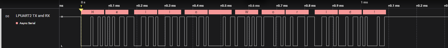
115200 bps: 1/115200 s per bit
8n1: 1 start bit + 8 data bits + no parity + 1 stop bit = 10 bits per frame
Total = 1024 * 10 * 1/115200 = 0.091 s
lpuart2_interrupt.h
#ifndef LPUART2_INTERRUPT_H
#define LPUART2_INTERRUPT_H

#include <MCXA153.h>

void lpuart2_init(const uint32_t baudrate);
void lpuart2_putchar(const int data);
int lpuart2_getchar(void);
uint32_t lpuart2_rxcnt(void);

#endif // LPUART2_INTERRUPT_H
lpuart2_interrupt.c
#include "lpuart2_interrupt.h"
#include "fifo.h"

// -----------------------------------------------------------------------------
// Local type definitions
// -----------------------------------------------------------------------------

// -----------------------------------------------------------------------------
// Local function prototypes
// -----------------------------------------------------------------------------

// -----------------------------------------------------------------------------
// Local variables
// -----------------------------------------------------------------------------
static fifo_t tx;
static fifo_t rx;
static uint8_t tx_buffer[128];
static uint8_t rx_buffer[128];

// -----------------------------------------------------------------------------
// Local function implementation
// -----------------------------------------------------------------------------
void lpuart2_init(const uint32_t baudrate)
{
    // Initialize FIFOs
    f_init(&tx, tx_buffer, sizeof(tx_buffer));
    f_init(&rx, rx_buffer, sizeof(rx_buffer));

    // Set clock source
    // MUX: [010] = FRO_HF_DIV (defaults: FRO_HF = 48 MHz; DIV = 1)
    MRCC0->MRCC_LPUART2_CLKSEL = MRCC_MRCC_LPUART2_CLKSEL_MUX(0b010);

    // HALT: [0] = Divider clock is running
    // RESET: [0] = Divider isn't reset
    // DIV: [0000] = divider value = (DIV+1) = 1
    MRCC0->MRCC_LPUART2_CLKDIV = 0;

    // Enable modules and leave others unchanged
    // LPUART2: [1] = Peripheral clock is enabled
    // PORT0: [1] = Peripheral clock is enabled
    MRCC0->MRCC_GLB_CC0_SET = MRCC_MRCC_GLB_CC0_LPUART2(1);
    MRCC0->MRCC_GLB_CC0_SET = MRCC_MRCC_GLB_CC0_PORT1(1);

    // Release modules from reset and leave others unchanged
    // LPUART2: [1] = Peripheral is released from reset
    // PORT0: [1] = Peripheral is released from reset
    MRCC0->MRCC_GLB_RST0_SET = MRCC_MRCC_GLB_RST0_LPUART2(1);
    MRCC0->MRCC_GLB_RST0_SET = MRCC_MRCC_GLB_RST0_PORT1(1);

    // Configure P1_4
    // LK : [1] = Locks this PCR
    // INV: [0] = Does not invert
    // IBE: [1] = Digital Input Buffer Enable, otherwise pin is used for analog
    //            functions
    // MUX: [0011] = Alternative 3 - LPUART2_RXD
    // DSE: [0] = low drive strength is configured on the corresponding pin,
    //            if the pin is configured as a digital output
    // ODE: [0] = Disables
    // SRE: [0] = Fast
    // PE:  [0] = Disables
    // PS:  [0] = n.a.
    PORT1->PCR[4] = PORT_PCR_LK(1) | PORT_PCR_MUX(3) | PORT_PCR_IBE(1);

    // Configure P1_5
    // LK : [1] = Locks this PCR
    // INV: [0] = Does not invert
    // IBE: [0] = Input buffer disable
    // MUX: [0011] = Alternative 3 - LPUART2_TXD
    // DSE: [0] = low drive strength is configured on the corresponding pin,
    //            if the pin is configured as a digital output
    // ODE: [0] = Disables
    // SRE: [0] = Fast
    // PE:  [0] = Disables
    // PS:  [0] = n.a.
    PORT1->PCR[5] = PORT_PCR_LK(1) | PORT_PCR_MUX(3);

    // Configure LPUART2. Although there are a lot of configuration options, the
    // default configuration takes the following steps:
    // 1. Configure baud rate
    // 2. Enable receiver and/or transmitter

    // 1.
    //
    // Configure baud rate
    // OSR: [01111] = Results in an OSR of 16 (15+1)
    // SBR: [.............] = baud rate = baud clock / ((OSR + 1) * SBR)
    //                        => SBR = baud clock / (baud rate * (OSR+1))
    LPUART2->BAUD = LPUART_BAUD_OSR(0b01111) |
       LPUART_BAUD_SBR(CLK_FRO_48MHZ / (baudrate * 16));

    // 2.
    //
    // TE: [1] = Transmitter Enable
    // TIE: [0] = Transmitter Disable
    // RE: [1] = Receiver Enable
    // RIE: [1] = Receiver Enable
    LPUART2->CTRL |= LPUART_CTRL_TE(1) | LPUART_CTRL_RIE(1) | LPUART_CTRL_RE(1);

    // Enable LPUART2 interrupts
    NVIC_SetPriority(LPUART2_IRQn, 3);
    NVIC_ClearPendingIRQ(LPUART2_IRQn);
    NVIC_EnableIRQ(LPUART2_IRQn);

    // Globally enable interrupts
    __enable_irq();
}

void lpuart2_putchar(const int data)
{
    // Wait for space to open up
    while(!f_push(&tx, (uint8_t)data))
    {}

    // Enable TDRE interrupt
    LPUART2->CTRL |= LPUART_CTRL_TIE(1);
}

int lpuart2_getchar(void)
{
    uint8_t c=0;

    // Wait for data.
    // If waiting is not desired, call the function lpuart2_rxqsize() first to
    // make sure data is available.
    while(!f_pop(&rx, &c))
    {}

    return (int)c;
}

uint32_t lpuart2_rxcnt(void)
{
    return f_cnt(&rx);
}

void LPUART2_IRQHandler(void)
{
    uint8_t c;

    // Clear the interrupt
    NVIC_ClearPendingIRQ(LPUART2_IRQn);

    // Data transmitted?
    if((LPUART2->STAT & LPUART_STAT_TDRE_MASK) != 0)
    {
        // Send another character?
        if(f_pop(&tx, &c))
        {
            LPUART2->DATA = c;
        }
        else
        {
            // FIFO is empty so disable TDRE interrupt
            LPUART2->CTRL &= ~(LPUART_CTRL_TIE(1));
        }
    }

    // Data received?
    if((LPUART2->STAT & LPUART_STAT_RDRF_MASK) != 0)
    {
        // Read data
        c = (uint8_t)(LPUART2->DATA);

        // Put in receive FIFO
        if(!f_push(&rx, c))
        {
            // Error: receive FIFO full!!
            // Should not happen, so freeze the system. Update FIFO size to
            // match your application.
            while (1)
            {}
        }
    }
}
Analyzer signal